



A Victron Cerbo GX wiring diagram looks busy, but most of its connections are thin data cables. The Cerbo GX doesn’t carry battery or load current. It only needs a small fused power feed, plus one cable from each Victron device it monitors. This guide walks through every connection type and the order to wire them.
Electrical work can be dangerous: follow the manual, fuse and size every cable correctly, and use a licensed electrician for anything connected to household wiring.

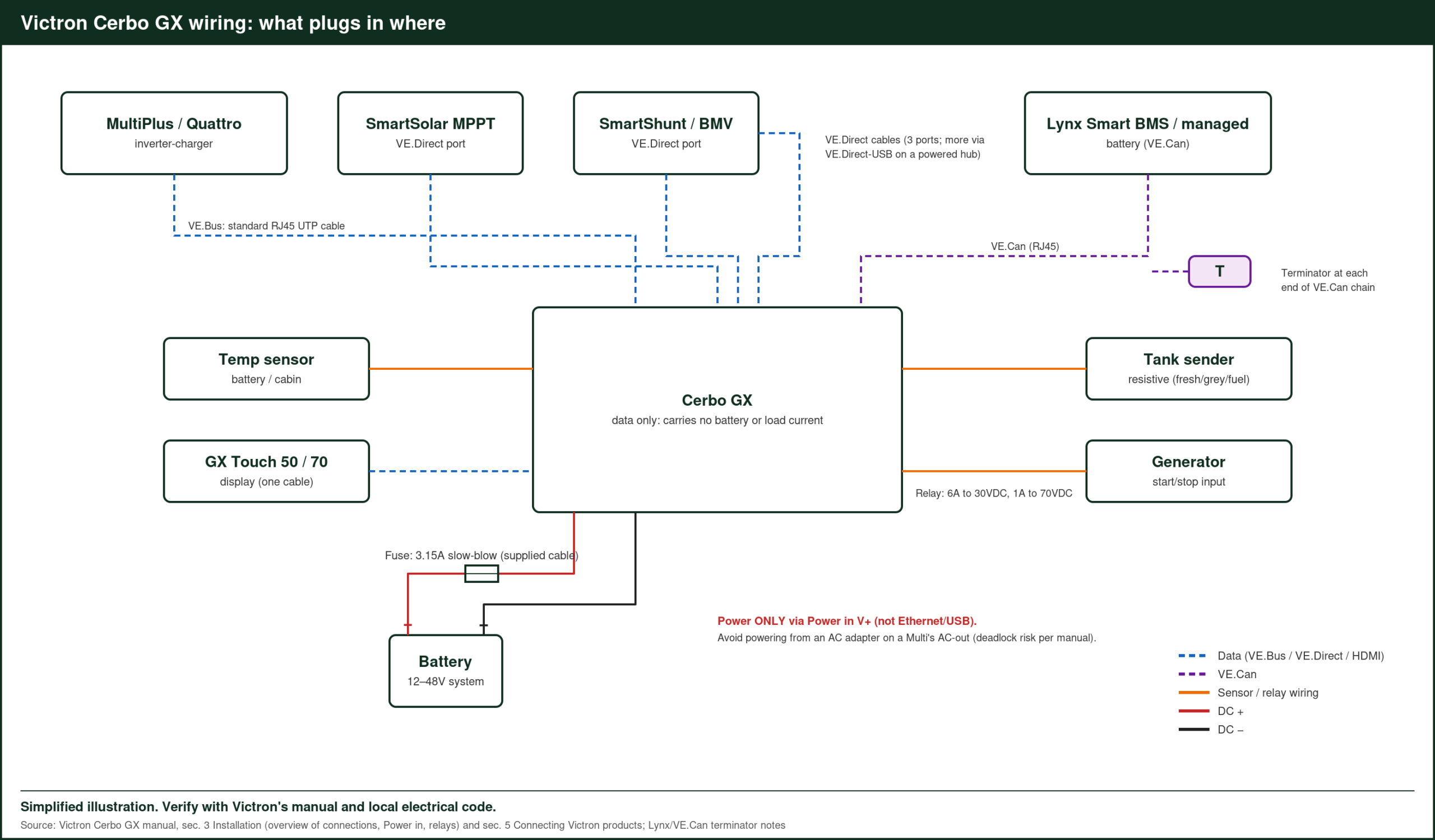
Victron Cerbo GX Wiring Diagram: Port by Port
| Connection (Cerbo GX MK2) | Count | Connects to |
|---|---|---|
| Power in | 1 (8–70VDC) | Fused DC feed; supplied cable has a 3.15A slow-blow fuse |
| VE.Bus | 1 (RJ45) | MultiPlus, MultiPlus-II, Quattro |
| VE.Direct | 3 | MPPTs, SmartShunt, BMV-712, Orion XS, Phoenix VE.Direct |
| VE.Can | 2 (VE.Can 1 isolated) | Lynx Smart BMS, managed lithium batteries, NMEA 2000 |
| Resistive tank inputs | 4 | Fresh, grey, black or fuel senders |
| Temperature inputs | 4 | Battery, cabin or fridge temperature |
| Digital inputs | 4 | Alarms, pulse counting, door sensors |
| Programmable relays | 2 | Generator start/stop; 6A up to 30VDC, 1A up to 70VDC |
| USB host | 3 | Extra VE.Direct devices via VE.Direct to USB |
| HDMI / GX Touch | 1 | GX Touch 50 or 70 |
Source: Victron Cerbo GX manual, MK2 overview of connections.
Wiring Order
- Mount it on a wall or DIN rail near the battery and devices, so data cables stay short.
- Connect data cables first: VE.Bus to the inverter-charger, VE.Direct to each MPPT and the shunt, and VE.Can to a BMS or managed battery.
- Terminate VE.Can. Fit an RJ45 terminator at each end of a VE.Can chain.
- Tank, temperature and relay connections next.
- Power last. Run a fused positive and negative from the battery or busbar.
- Connect to Wi-Fi or Ethernet and register on VRM.
Common Wiring Mistakes
- Powering it from the AC output. Victron’s manual says power comes only through the Power in terminal (8–70VDC), not Ethernet or USB.
- Missing terminators on VE.Can, which causes dropouts.
- Expecting VE.Bus over Bluetooth. VE.Bus needs a cable to the GX device, or the separate VE.Bus Smart dongle for phone access.
- More VE.Direct devices than ports. The MK2 has three; add more with VE.Direct to USB adapters, which Victron says should go through a powered USB hub.
After Wiring
In the Cerbo’s settings, set your battery monitor source, enable DVCC if your battery maker recommends it, and confirm every device appears in the device list.
Victron lists every Cerbo GX variant, with datasheets, on its official product page.
Worked Example: A Van System Wired to a Cerbo GX
A van with a MultiPlus-II, a SmartSolar MPPT, an Orion XS, a SmartShunt and a fresh water tank sender:
| Device | Cerbo connection |
|---|---|
| MultiPlus-II | VE.Bus (RJ45 cable) |
| SmartSolar MPPT | VE.Direct 1 |
| SmartShunt | VE.Direct 2 |
| Orion XS | VE.Direct 3 |
| Fresh water tank sender | Resistive tank input 1 |
| GX Touch 50 | HDMI / GX Touch port |
| Power | Fused feed from the DC busbar |
All three VE.Direct ports are used, so any future VE.Direct device would connect through a VE.Direct to USB cable.
Worked Example: A Home Battery System
A home with two MultiPlus-II units in split phase, a Lynx Smart BMS and two SmartSolar MPPTs:
- VE.Bus: one cable from the Cerbo to the first MultiPlus-II; the units link to each other.
- VE.Can: the Lynx Smart BMS, with terminators at both ends of the chain.
- VE.Direct: each MPPT on its own port.
- Relay 1: generator start/stop wired to the generator’s remote start input.
- Ethernet: to the home router for VRM.
Power Feed Details
The Cerbo GX draws only a small current, but its power cable needs its own fuse, and the supplied cable includes a 3.15A slow-blow inline fuse. Take the feed from a point that stays live when loads are switched off, such as the battery side of the main switch or a dedicated fused circuit, so the Cerbo keeps logging and can show alarms. On systems with a BMS, the GX-Power output on some Victron BMS units can supply it.
Using the Relays for Generator Start
Relay 1 can be set to start and stop a generator automatically by battery state of charge, battery voltage, AC load or inverter warnings. Wire it to the generator’s two-wire remote start input, following the generator’s manual. The relay is rated 6A up to 30VDC, so for generators that need more current to start, use the relay to switch an intermediate relay.
Tank and Temperature Inputs
The four resistive tank inputs accept common tank senders; you set the sender type and tank capacity in the Cerbo’s settings. The temperature inputs use Victron temperature sensors and can show battery, cabin or fridge temperatures on the dashboard and in VRM, with alarms if a value goes out of range.
Checking Everything After Wiring
- Power up and open the device list on the GX Touch or Remote Console.
- Confirm each connected product appears with the right name.
- Select the battery monitor in Settings → System setup.
- Enable VRM and confirm data arrives in the portal.
- Test the relays and inputs one by one.
FAQ
Does the Cerbo GX need its own fuse?
Yes. The supplied power cable includes a 3.15A slow-blow inline fuse.
Which cable connects a MultiPlus to a Cerbo?
A standard RJ45 network cable into the VE.Bus port.
Can I add a screen later?
Yes. The GX Touch connects with one cable.
Can the Cerbo GX power itself from a 48V battery?
Yes. Its power input accepts 8–70VDC, so it runs directly from 12V, 24V or 48V systems.
Do I need Ethernet, or is Wi-Fi enough?
Either works for VRM. Ethernet is the most dependable, while built-in Wi-Fi suits installs where running a cable isn’t practical.
Sources: Victron Cerbo GX manual (installation chapter), Cerbo GX product page and MultiPlus-II 120V datasheet (victronenergy.com, accessed Oct 2026); Mobile Solar Consulting, “Victron Cerbo GX Ports EXPLAINED! (What & Where to Connect)”.
Related: Klein CL390 Clamp Meter Solar Panel Test, Proster Voltage Tester Pen Review, weBoost Home MultiRoom Review, plus the Victron Energy Guide