



Victron Lynx Distributor wiring looks intimidating, but it’s really a set of busbars that bolt together. Victron’s manual lays out the module order, grounding, fusing and a commissioning checklist. Here’s that process in plain steps, plus the system layouts Victron shows.

Electrical work can be dangerous: follow the manual, fuse and size every cable correctly, and use a licensed electrician for anything connected to household wiring.
Victron Lynx Distributor Wiring: The Modules
| Module | Job |
|---|---|
| Lynx Power In | Busbar with 4 battery or DC connections, no fuses |
| Lynx Class-T Power In | Fuses up to 2 battery strings with Class-T fuses |
| Lynx Shunt VE.Can | Main fuse holder plus battery monitor, VE.Can to a GX device |
| Lynx Smart BMS | Contactor, BMS and battery monitor for Victron Lithium Smart batteries |
| Lynx Distributor | 4 MEGA-fused outputs with fuse monitoring |
Source: Victron Lynx Distributor manual, “The Lynx Distribution System”.
Typical Layouts From the Manual
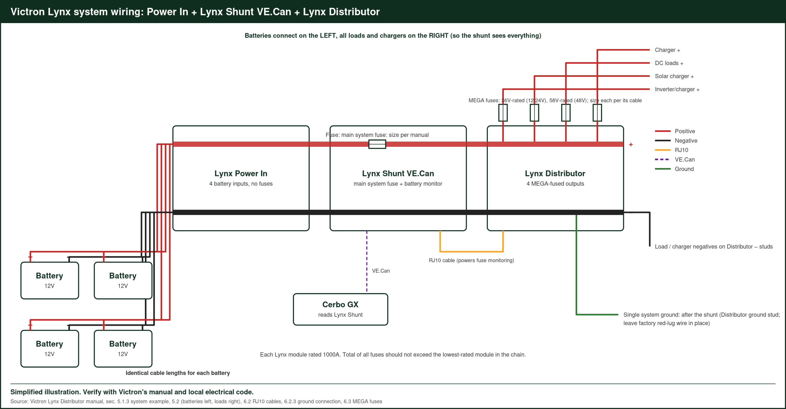
- Lead acid: batteries > Lynx Power In > Lynx Shunt VE.Can (main fuse + monitor) > Lynx Distributor > inverter, chargers, loads. A Cerbo GX reads the shunt.
- Victron lithium: batteries > Lynx Smart BMS > two Lynx Distributors.
- Simple: batteries and loads on a Lynx Distributor only.
Step by Step
- Plan the order. Modules join left to right with the busbars. Check each module’s orientation before mounting.
- Mount and join the modules. Interconnect the busbars, then fit the RJ10 cable from the Shunt or BMS to each Distributor. The cable powers the fuse-monitoring electronics.
- Address the Distributors (with a Lynx Smart BMS) so each reports as A, B, C or D.
- Ground once. Make a single ground connection per system, after the shunt or BMS. Leave the factory red-lug wire on the Distributor’s ground stud in place.
- Connect the negatives. Flip up the cable separators and remove the separator post if the cable is thicker than 10mm.
- Fit the fuses. Check the middle-row bottom nuts are at 10Nm, then fit all four MEGA fuses (36V-rated for 12/24V, 58V-rated for 48V) at 14Nm. Use dummy fuses in unused slots.
- Connect the positives last.
Commissioning Checklist (From Victron)
- Check the polarity and cross-section of every DC cable.
- Check that every lug is properly crimped, then tug-test each battery cable.
- Check all connections are tight without exceeding the maximum torque.
- Check fuse names in VictronConnect if you’re using a Lynx Smart BMS.
Sizing Notes
Each Lynx module is rated 1000A, or 12kW at 12V. The total of all fuses shouldn’t exceed the lowest-rated module in the chain. Size each cable for its fuse and run length using Victron’s Wiring Unlimited book.
Victron’s Lynx Distributor product page has the full datasheet and manual downloads.
Worked Example: A 12V Van Lynx Build
A 12V van with two 200Ah lead-acid or third-party lithium batteries, a MultiPlus-II 12/3000, a SmartSolar 100/50, an Orion XS 12/12-50A and a DC fuse block:
- Lynx Power In: both battery positives and negatives land here.
- Lynx Shunt VE.Can: carries the main fuse and measures battery current for state of charge.
- Lynx Distributor: four MEGA-fused outputs.
| Distributor slot | Load | Approx. current (est.) | Fuse (example) |
|---|---|---|---|
| 1 | MultiPlus-II 12/3000 | ≈ 270A at full inverter load | 300–400A per inverter manual |
| 2 | SmartSolar 100/50 | 50A | 60A |
| 3 | Orion XS 12/12-50A | 50A | 60A |
| 4 | DC fuse block | ≈ 40A | 60A |
Example values; always use the fuse ratings in each product’s manual and size cables to match. The fuse total here is well under the 1000A module rating.
Worked Example: Checking the Fuse Total
Victron’s manual says the combined fuse ratings shouldn’t exceed the lowest-rated module. With the 12V example above: 400 + 60 + 60 + 60 = 580A, below the 1000A Lynx rating. If you add a second Distributor for more circuits, add its fuses into the same total.
Choosing MEGA Fuse Ratings
Each fuse protects the cable leaving that slot, so pick it for the cable’s ampacity and the load’s maximum current:
- Inverter or inverter-charger: use the DC fuse rating in the inverter’s manual.
- Chargers: a little above the charger’s maximum output.
- Fuse blocks or panels: sized for the feed cable to that panel.
Remember the voltage rating: 36V-rated MEGA fuses for 12V and 24V systems, 58V-rated for 48V, per the manual.
Grounding and Negative Cabling
All negatives return through the same Lynx chain, which keeps the shunt in the measurement path. The single system ground goes after the shunt or BMS, which means every current the batteries supply or receive passes through the shunt and is counted in the state of charge.
Torque and Tidy Cable Runs
The manual’s torque values (10Nm for the middle-row bottom nuts and 14Nm for fuse bolts) matter on busbars carrying hundreds of amps. A torque wrench gets them right and avoids over-tightening. Route cables so they enter the Lynx straight and are supported close to the lugs, which keeps strain off the connections.
Monitoring the Lynx System
With a Lynx Shunt VE.Can or Lynx Smart BMS connected to a Cerbo GX, you can see battery state of charge, current and fuse status on the GX Touch and in VRM. If a fuse opens, the Distributor’s fuse monitoring reports it, which makes it quick to find the affected circuit.
Expanding Later
The modular design makes growth simple: add another Lynx Distributor for more fused circuits, or swap a Lynx Power In for a Lynx Smart BMS if you move to Victron lithium. Leave space on the mounting board at either end of the chain so new modules can bolt on without moving the rest.
FAQ
Do I need a main fuse before the Lynx?
Yes. Put a main system fuse in the Lynx Shunt VE.Can or Class-T Power In, or fit an external fuse near the battery.
Can I use a Lynx Distributor without a Lynx shunt?
Yes. It works on its own as a fused busbar. You’d then use a separate battery monitor, such as a SmartShunt, on the negative side.
What size cable joins the battery to the Lynx Power In?
Size it for the main fuse rating and run length, following Victron’s Wiring Unlimited guidance.
Sources: Victron Lynx Distributor M8 and M10 manual (“System design”, “Installation”, “Commissioning”), victronenergy.com, accessed Oct 2026.
Related: Klein CL390 Clamp Meter Solar Panel Test, LiTime 12V 50Ah LiFePO4 Battery Review, MHPOWOS Solar Battery Trickle Charger Review, plus the Victron Energy Guide