



If you’re searching for a Victron isolation transformer wiring diagram, you probably want to know where the transformer sits between the shore pedestal and your boat’s AC panel, and what happens to the ground wire. This guide explains the layout and the reasoning behind it from Victron’s datasheet. The actual connections must follow the installation manual and your local marine code.
Electrical work can be dangerous: follow the manual, fuse and size every cable correctly, and use a licensed electrician for anything connected to household wiring.
Why an Isolation Transformer?
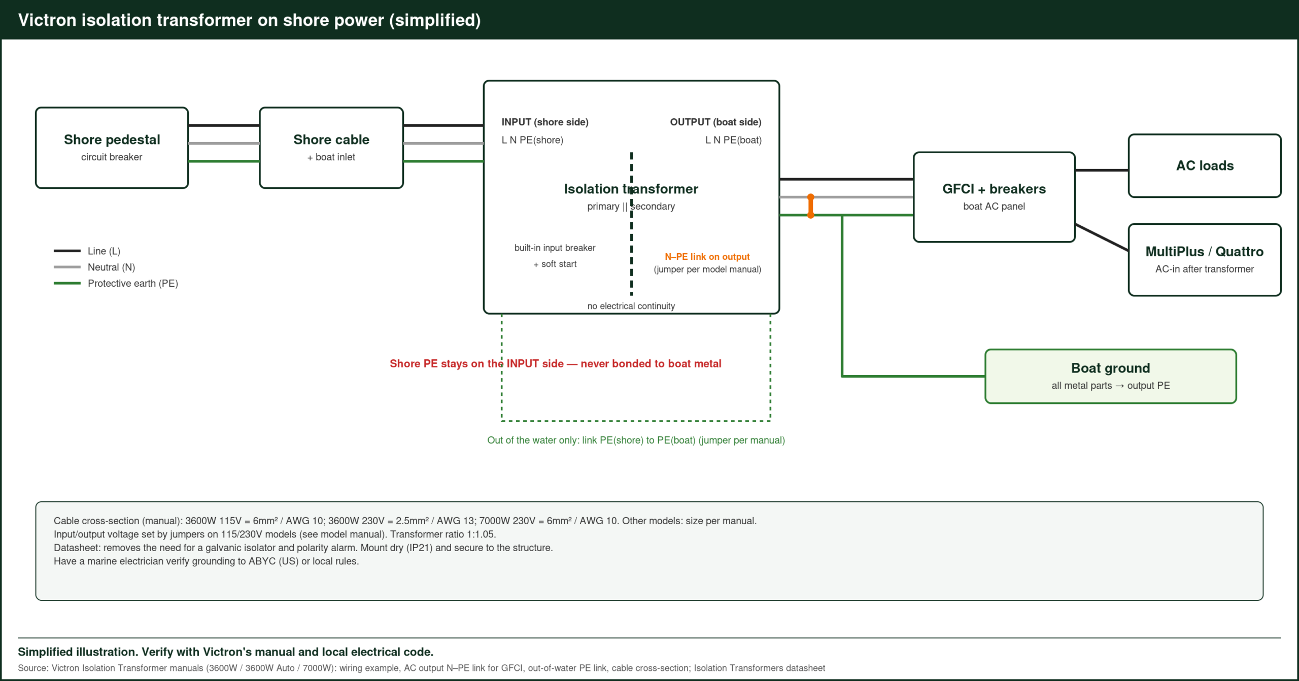
Victron’s datasheet says an isolation transformer “eliminates any electrical continuity between AC shore power and the boat.” Shore power feeds the transformer’s primary side, and the boat connects only to the secondary. The shore ground never reaches the boat’s metal parts, so it can’t drive galvanic corrosion. Victron also says this removes the need for galvanic isolators and polarity alarms.
Victron Isolation Transformer Wiring Diagram: The Layout
- Shore pedestal → shore cord → boat inlet.
- Inlet → transformer primary. Victron’s transformers have a built-in input circuit breaker.
- Transformer secondary → boat AC panel. On the secondary side, Victron says to connect all metal parts to the transformer’s neutral output. That way a GFCI will trip, or a fuse will blow, if there’s a short circuit.
- Boat AC panel → inverter/charger and loads. A MultiPlus or Quattro AC input goes here, after the transformer.
Victron also recommends connecting the secondary neutral to ground when the boat is out of the water, for the best safety.
Model Ratings
| Model | Input/ | Rating |
|---|---|---|
| 2500W | 115V or 230V | 22A / 11A |
| 4500W | 115V or 230V | 38A / 19A |
| 4500W Auto | Auto-selects 115V or 230V | 38A / 19A |
| 8000W | 230V | 35A |
Source: Victron Isolation Transformers 2500/4500/8000 datasheet.
The 2500W and 4500W models can be wired as 115V to 115V, 230V to 230V, 115V to 230V or 230V to 115V. The Auto model switches to 115V for supplies of 88–130V and to 230V for 185–250V, and raises the output by a 1:1.05 ratio.
Soft Start
Every Victron isolation transformer has soft start built in. It stops the inrush current from blowing the shore power fuse when you plug in.
Install Tips
- Size the transformer to your inlet. A 30A 120V inlet points to the 4500W model (38A at 115V).
- Ventilation: the aluminum case is rated IP21, so mount it somewhere dry.
- Weight: 12.1kg to 28.17kg, so mount it to the structure.
- Have a marine electrician check the grounding to ABYC rules.
You can download the isolation transformers manual and datasheet from Victron Energy’s website.
Wiring Order, Step by Step
This is the general order of work shown in Victron’s manuals. Your electrician will follow the exact terminal layout for your model.
- Turn off and unplug shore power. Confirm the inlet is dead with a tester.
- Mount the transformer on a solid, dry surface with space around the case for airflow.
- Run the input cable from the shore inlet to the transformer’s input terminals: line, neutral and the shore ground.
- Set the voltage links for your input and output voltages (115/115, 230/230, 115/230 or 230/115) on the 2500W and 4500W models. The Auto model selects its input range on its own.
- Run the output cable from the secondary to the boat’s main AC breaker panel.
- Bond the secondary. Connect the boat’s ground and all metal parts to the secondary neutral output, as Victron describes.
- Test before use. Check that a fault on the boat side trips the GFCI or fuse, then plug in and confirm voltage at the panel.
The Ground Wire, Explained Simply
On a normal shore connection, the boat’s green ground wire runs all the way back to the marina. Any small voltage between your boat and other boats travels along it and through the water, which wears away zincs and underwater metal. With an isolation transformer, the shore ground ends at the primary side. The boat’s ground is created fresh on the secondary side by bonding it to the secondary neutral. That’s why the transformer replaces a galvanic isolator.
Worked Example: Sizing Cable Runs
Cable size depends on current and distance, so pull the figures from the manual’s table and your local code. As a rough guide:
| Model and voltage | Rated current | What that means for wiring (estimate) |
|---|---|---|
| 2500W at 115V | 22A | Similar to a 30A shore cord circuit |
| 4500W at 115V | 38A | Heavier than a 30A circuit, so size for the transformer’s breaker |
| 4500W at 230V | 19A | Lighter cable than the 115V setup for the same power |
| 8000W at 230V | 35A | Size for a 32A-class circuit |
Estimates for orientation only; follow the manual and local code.
Adding a MultiPlus or Quattro
The inverter/charger goes after the transformer and the boat’s AC panel feeds it as usual. Two things to plan:
- AC input current limit: set it in VictronConnect to match the transformer and shore supply, so the charger and loads don’t overload the pedestal.
- PowerAssist: lets the inverter top up from the batteries when loads briefly exceed what shore power can supply.
Final Checks
- Labels on the AC panel show which circuits are fed from the transformer.
- The transformer’s input breaker is reachable.
- The case isn’t in a bilge or exposed to spray (IP21).
FAQ
Does the shore ground connect to the boat?
No. The shore ground stays on the primary side. The boat’s ground connects to the secondary neutral.
Can it convert 230V marina power to 120V?
Yes. The 2500W and 4500W models can be wired for 230V to 115V.
Where does the soft start fit in the wiring?
It’s built into the transformer, so there’s nothing extra to wire. It limits the inrush current when you plug in.
Should I connect the secondary neutral to ground on the hard?
Victron recommends it when the boat is out of the water, for the best safety.
Can one transformer feed both a MultiPlus and other AC loads?
Yes. Both connect on the secondary side, through the boat’s AC panel.
Sources: Victron Isolation Transformers datasheet (2500, 4500, 8000W) and product page, victronenergy.com, accessed Oct 2026.
Related: EcoFlow Delta 3 Max Generator Charging, Allwei 1500W Pure Sine Wave Inverter Review, Klein CL390 Clamp Meter Solar Panel Test, plus the Victron Energy Guide