



This guide covers Victron Battery Protect wiring and settings for the Smart BatteryProtect 65A, 100A and 220A, using the steps in Victron’s manual. Wired correctly, it disconnects your DC loads at a voltage you choose. Wired wrong, it can trip constantly or be damaged, most often by an inverter connected through it.
Electrical work can be dangerous: follow the manual, fuse and size every cable correctly, and use a licensed electrician for anything connected to household wiring.
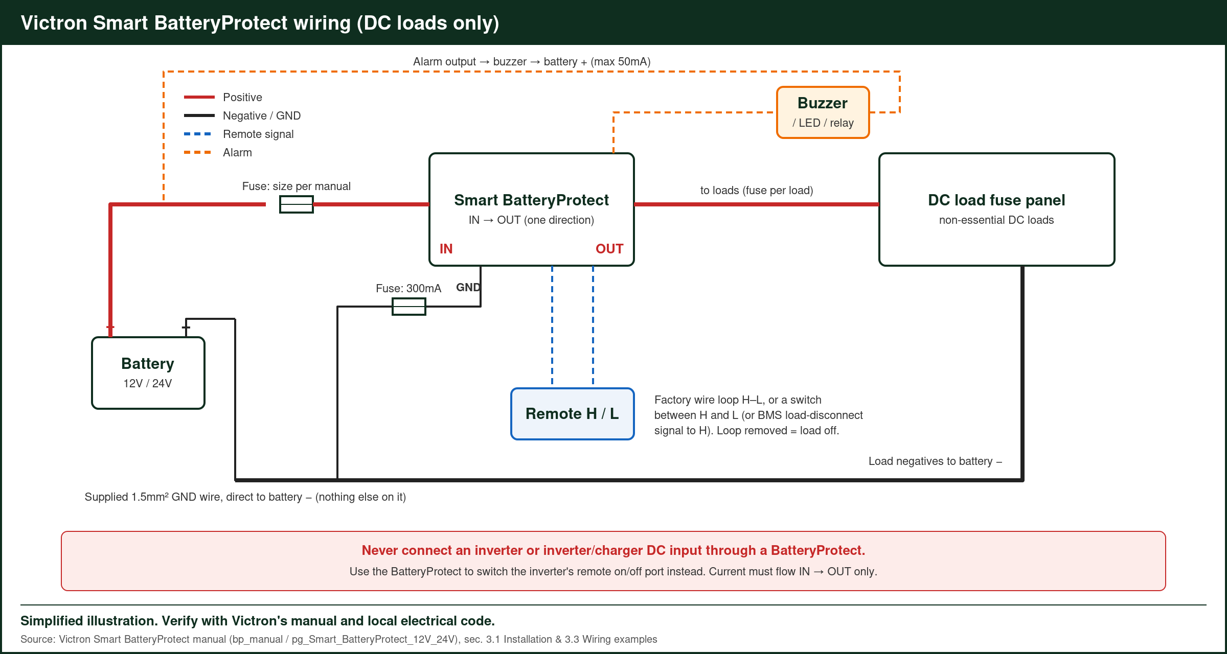
Victron Battery Protect Wiring: Basic Diagram
Battery positive → fuse → IN terminal → BatteryProtect → OUT terminal → DC load panel.
The GND wire goes straight to battery negative (or vehicle chassis).
- Mount it close to the battery. Victron says within 50cm, in a ventilated spot, but not directly above the battery because of possible corrosive gases.
- Fuse the battery cable. Fit a properly sized fuse between the battery positive and the IN terminal, following local rules.
- Respect the direction. Current may only flow from IN (battery) to OUT (load). Reverse current damages the unit.
- Connect the GND wire. Use the supplied 1.5mm² wire directly to battery negative, with nothing else on it. Victron says a 300mA fuse is enough to protect it.
- Program before you connect the load output. Victron’s manual says not to connect OUT until programming is finished.
- Size the cable to the load. A long or thin cable between battery and IN can cause a false short-circuit alarm at start-up.
The Inverter Rule
Don’t wire an inverter or inverter-charger’s DC input through a BatteryProtect. Victron forbids it: the inverter’s capacitors trip the short-circuit protection, and reverse current may damage the unit. Instead, wire the inverter directly to the battery (fused) and use the BatteryProtect’s control to switch the inverter’s remote on/off port.
Remote and Alarm Wiring
- Remote on/off: connect a switch between Remote H and Remote L, or switch H high (to battery positive) or L low (to battery negative). This lets the unit double as a system on/off switch.
- Alarm output: connect a buzzer, LED or relay between the alarm terminal and battery positive, 50mA maximum.
Settings
| Setting | Default or option |
|---|---|
| Disconnect / reconnect | 10.5V / 12V on 12V systems (21V / 24V on 24V), adjustable |
| Mode A | Buzzer or LED alarm (default) |
| Mode B | Relay alarm |
| Mode C | Li-ion: controlled by an external lithium BMS |
| Disconnect delay | 90 seconds (immediate when triggered by a VE.Bus BMS) |
| Reconnect delay | 30 seconds |
| Overvoltage cut-off | 16.3V / 32.6V |
Set these in VictronConnect, or use the PROG pin method with the nine preset levels in the manual.
Victron lists every Smart BatteryProtect variant, with datasheets, on its official product page.
Choosing the Right Size
| Model | Continuous load current | Typical use |
|---|---|---|
| Smart BatteryProtect 65A | 65A | Van and small RV DC panels |
| Smart BatteryProtect 100A | 100A | Larger RV and boat DC loads |
| Smart BatteryProtect 220A | 220A | Big DC distribution, high-current DC loads |
Add up the DC loads that can run at the same time, such as a fridge, water pump, lights, fans and a diesel heater, and pick a model with margin above that total.
Worked Example: A Van DC Panel on a 65A Unit
A 12V van with a compressor fridge (5A average, higher when starting), a water pump (6A), LED lights (3A), a roof fan (3A) and USB chargers (4A). Worst case is about 21A, or roughly 25A with the fridge compressor starting (estimates). The 65A Smart BatteryProtect covers that with plenty of headroom.
- Lead-acid battery: set the disconnect at 11.5V and reconnect at 12.5V to avoid deep discharge (example values).
- Lithium battery with internal BMS: set the disconnect a little above the BMS’s own low-voltage cut-off, for example 12.0V, so the BatteryProtect switches loads off first (example values; follow your battery maker’s figures).
Worked Example: Controlling an Inverter Without Wiring It Through
A 12V system with a Phoenix inverter. The inverter connects directly to the battery through its own fuse. A small wire from the BatteryProtect’s OUT terminal (or its alarm output, set as a relay) goes to the inverter’s remote on/off input, so the BatteryProtect switches the inverter off at the same disconnect voltage as the DC loads, without carrying the inverter’s current. Check the inverter’s manual for how its remote input is wired.
Mode C With a Lithium BMS
In Mode C, a Victron BMS such as the smallBMS, VE.Bus BMS or Lynx Smart BMS controls the BatteryProtect through the remote terminals. When a cell gets too low, the BMS switches the loads off, and when the battery recovers, it switches them back on. That gives cell-level protection rather than relying only on the total battery voltage.
Using a BatteryProtect as a Charge Disconnect
Turned around so that charge current flows from IN to OUT, a BatteryProtect can disconnect a charger that has no remote on/off input, such as a simple alternator feed. In a lithium system, the BMS’s charge disconnect output controls it. Victron’s manual shows this two-BatteryProtect layout, with one for loads and one for charging.
Programming With VictronConnect
- Wire the IN, GND and battery fuse, leaving OUT disconnected.
- Open VictronConnect and connect over Bluetooth.
- Choose the battery voltage, disconnect and reconnect levels, and the alarm mode.
- Save, then connect the OUT cable to the load panel.
- Watch the status screen to confirm the output is on and shows the expected voltage.
FAQ
Can I use it to disconnect a charger?
Yes, if it’s turned so charge current flows from IN to OUT. Victron shows a two-BatteryProtect setup for load and charger control in the manual.
Why does it trip when a load starts?
Usually the battery cable is too thin or too long, or there are capacitive loads on the output.
Does the BatteryProtect use power itself?
It draws very little; check the datasheet for the exact consumption figures in on and off states.
Can I switch it manually?
Yes. A switch across the remote terminals turns the output on and off, so it can double as a main DC load switch.
Sources: Smart BatteryProtect 12/24V manual and datasheet (victronenergy.com).
Related: LiTime 12V 50Ah LiFePO4 Battery Review, Pro Chaser 400W Car Power Inverter Review, EcoFlow Delta 3 Max Van Life Leisure Battery, plus the Victron Energy Guide